
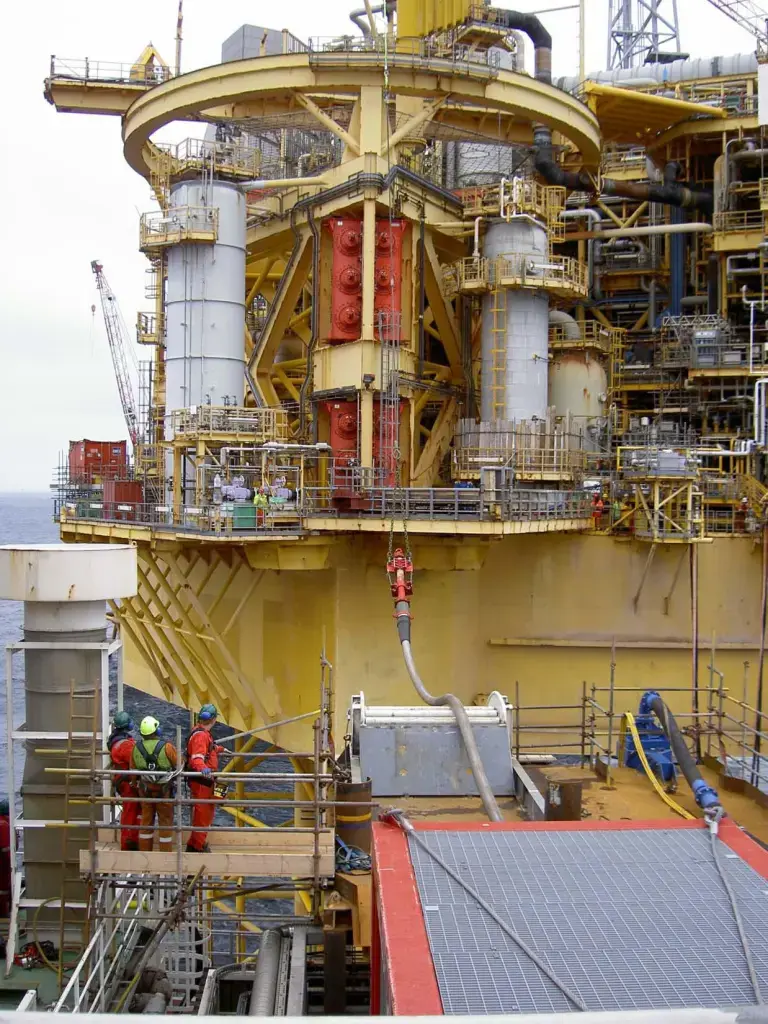
May 13, 2012 – Test for the forthcoming well intervention operation on the G4 well
May 13, 2012 - During testing for the forthcoming well intervention operation on the G4 well, a crane on Elgin’s PUQ (Process Utilities Quarters) platform manoeuvres into position the Coflex hose through which heavy mud will be pumped into the well from the West Phoenix drilling rig. From the receiving connection on the PUQ, the mud flows via a temporary ‘chiksan’ pipeline into the G4 wellhead.
Download the photo
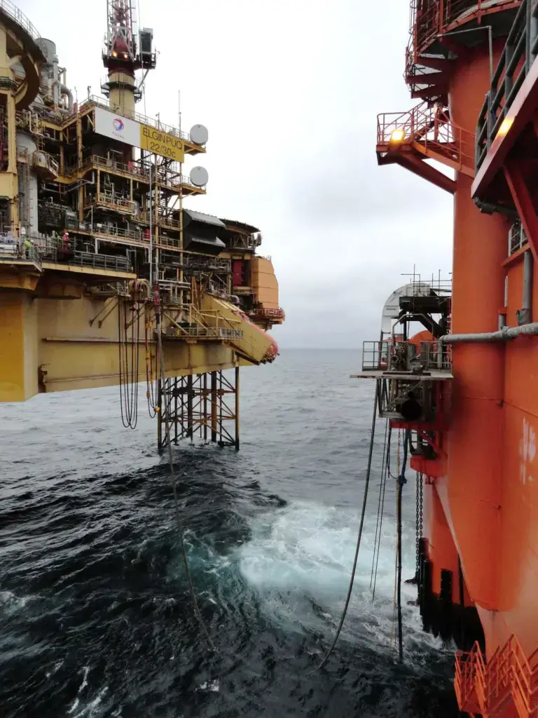
May 13, 2012 – Test for the forthcoming well intervention operation on the G4 well
May 13, 2012 - During testing for the forthcoming well intervention operation on Elgin’s G4 well, the Coflex hose through which heavy mud will be pumped into the well is connected from the West Phoenix drilling rig to Elgin’s PUQ (Process Utilities Quarters) platform; it is normal for the Coflex to dip into the sea en route. From the receiving connection on the PUQ, the mud flows via a temporary ‘chiksan’ pipeline into the G4 wellhead.
Download the photo

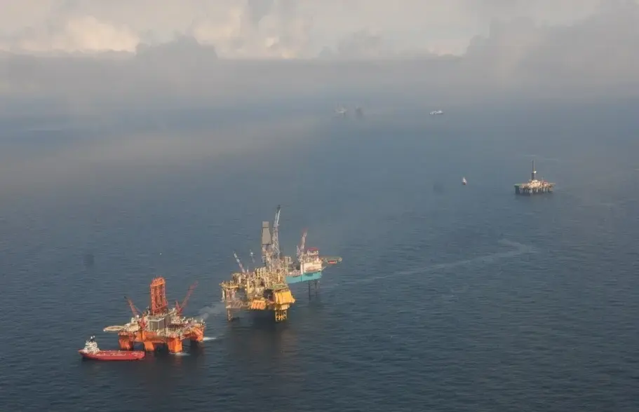
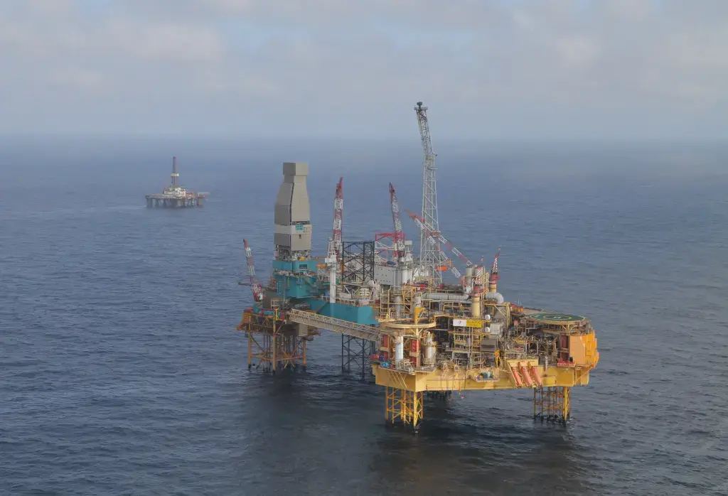
May 10, 2012 - Final preparations for the planned G4 well intervention
May 10, 2012 – The West Phoenix drilling rig positioned about 30 metres away from the Elgin complex ready to support the operation. In the background, the Sedco 714 rig drilling the first relief well.
Download the photo

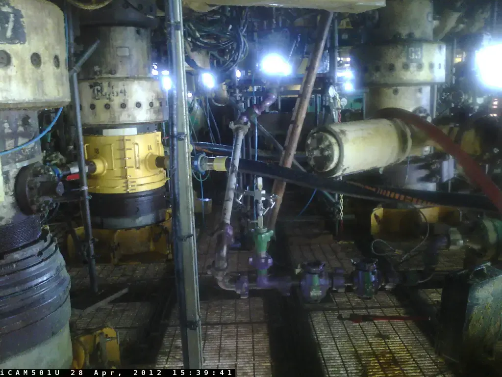
April 28, 2012 – G4 wellhead ready for the forthcoming well intervention operation
April 28, 2012 - The G4 wellhead ready for the forthcoming well intervention operation, with the flexible diverter hose (black & yellow) directing leaking gas away from the area and the temporary pipeline (grey with purple joints) in position to receive the heavy mud that will be pumped into the well from de Well Phoenix.
Download the photo

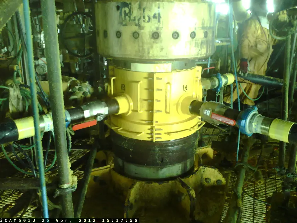
April 25, 2012 – Installation of diverter: a key step in improving safety of the G4 well intervention
April 25, 2012 - A key piece of equipment has been installed on the G4 well. Known as a “diverter”, this specially manufactured device connects to the wellhead and diverts the flow of leaking gas, via four flexible hoses, away from the wellhead and the platform. This improves the safety of the well intervention operation by avoiding the possibility of gas accumulating in the work area around the G4 wellhead.
Download the photo

April 18, 2012 - Elgin complex with the Rowan Viking rig and the Sedco 714 rig
April 18, 2012 - The Elgin complex with the Rowan Viking rig alongside the Well Head Platform A (WHPA). The Sedco 714 rig is in the background drilling the first relief well.
Download the photo

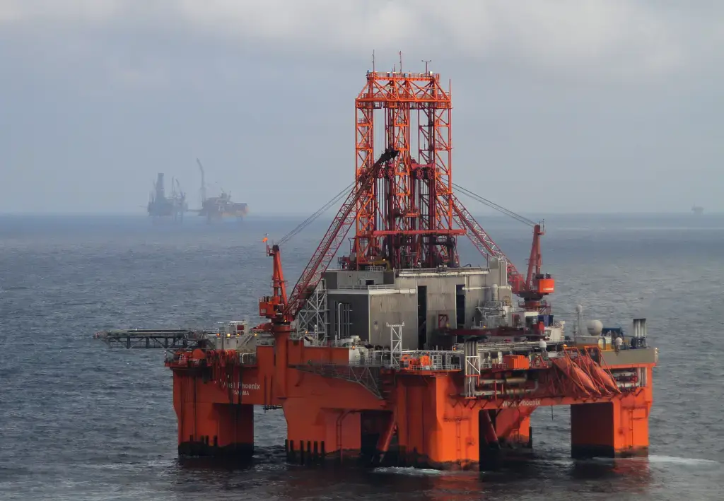
April 18, 2012 - The West Phoenix drilling rig on standby near the Elgin complex
April 18, 2012 - The West Phoenix drilling rig, which has been mobilised for the G4 well intervention operation, on standby near the Elgin complex.
Download the photo

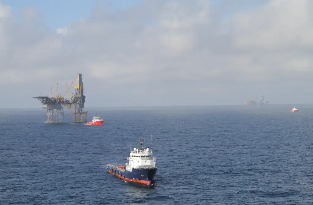
April 18, 2012 - Supply vessels near the Rowan Gorilla V rig
April 18, 2012 - Supply vessels near the Rowan Gorilla V rig, which is currently suspending operations on the West Franklin field.
Download the photo

April 17, 2012 - The Elgin Well Head Platform A (WHPA) where the G4 well is located
April 17, 2012 - The Elgin Well Head Platform A (WHPA) where the G4 well is located; various indications suggest the gas leak rate has decreased - the Rowan Viking rig is at the left.
Download the photo

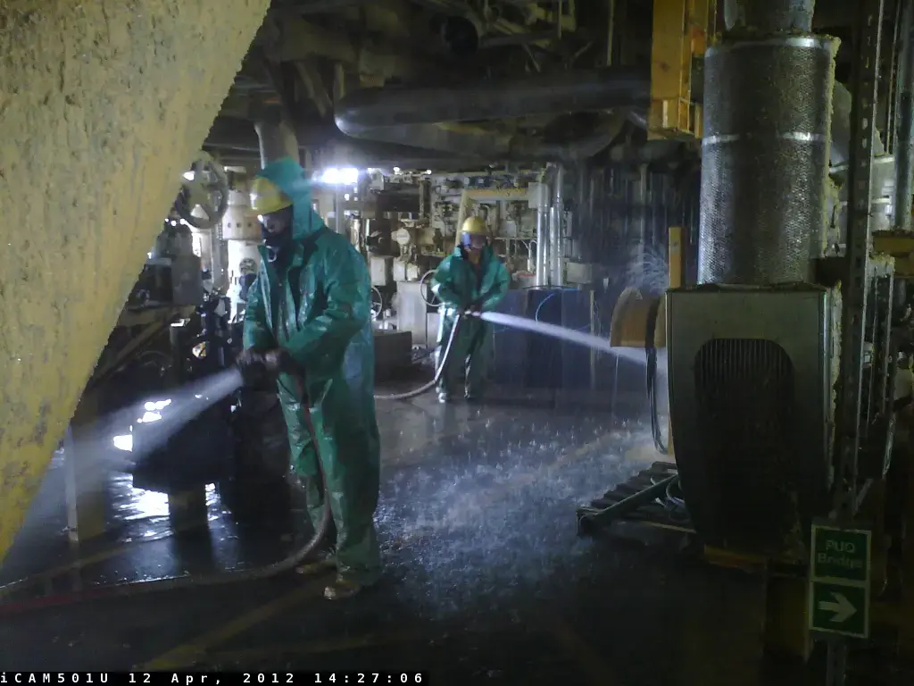
April 12, 2012 - Cleaning operations on Elgin wellhead platform
April 12, 2012 - Cleaning operations being conducted on Elgin wellhead platform.
Download the photo

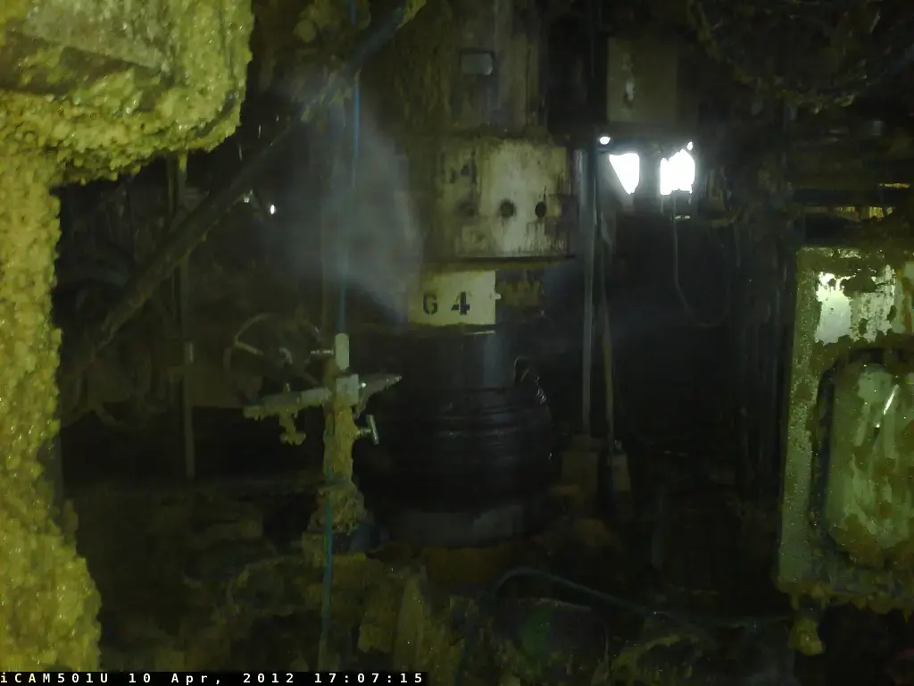
April 10, 2012 - Elgin G4 wellhead being cleaned
April 10, 2012 - Elgin G4 wellhead being cleaned, with leaking gas flume visible.
Download the photo

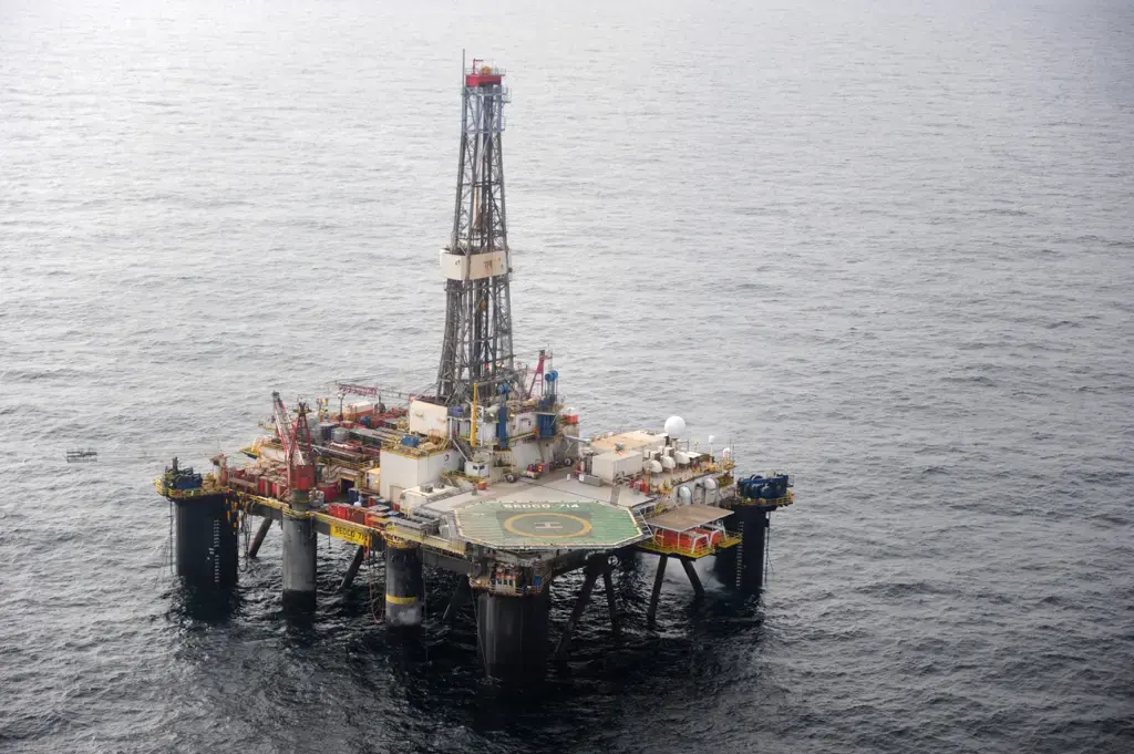
Sedco 714 semi-submersible drilling rig
Sedco 714 semi-submersible drilling rig. The rig, which is expected to start drilling the first relief well, arrived at a standby location outside the Elgin exclusion zone on April 8th. This is expected to be within a few days. (archives image)
Download the photo

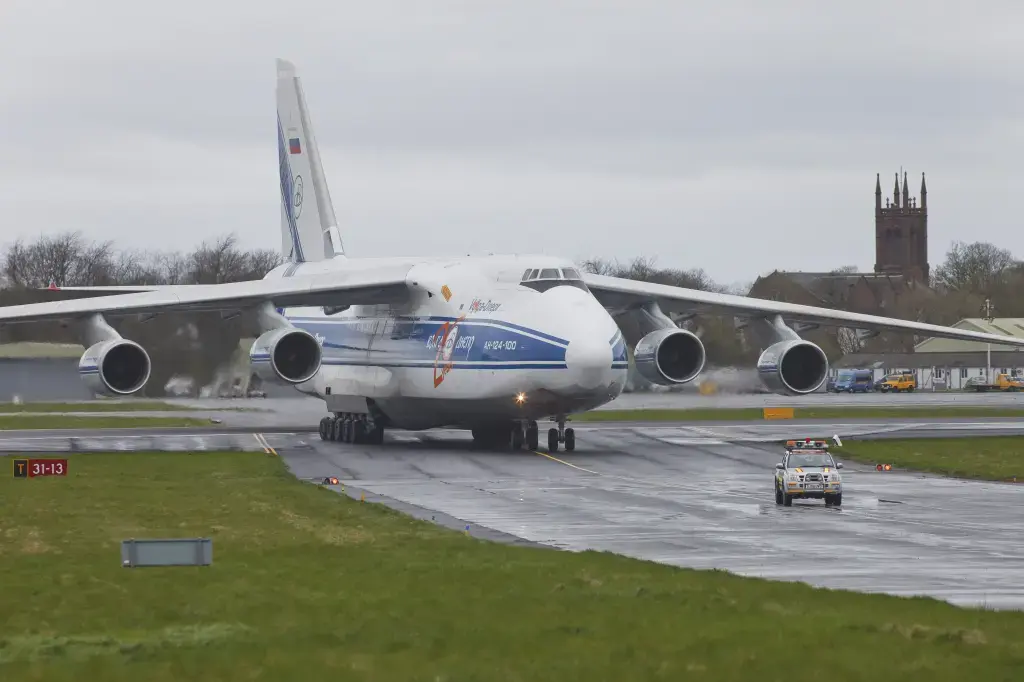
April 6, 2012 - An Antonov 124 aircraft arrived at Prestwick Airport
An Antonov 124 aircraft arrived at Prestwick Airport from Houston on Friday, April 6, carrying specialized equipment in preparation for well intervention operations.
Download the photo

April 6, 2012 - An Antonov 124 aircraft arrived at Prestwick Airport
An Antonov 124 aircraft arrived at Prestwick Airport from Houston on Friday, April 6, carrying specialized equipment in preparation for well intervention operations.
Download the photo

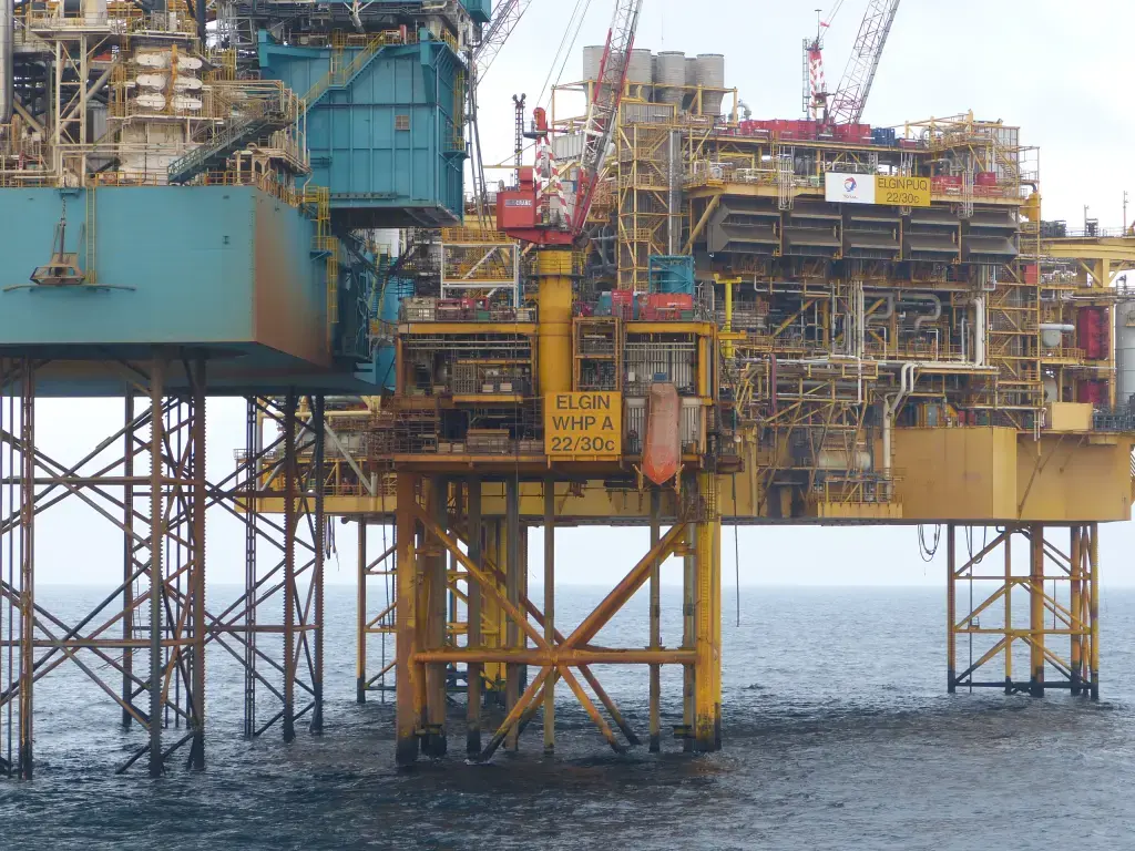
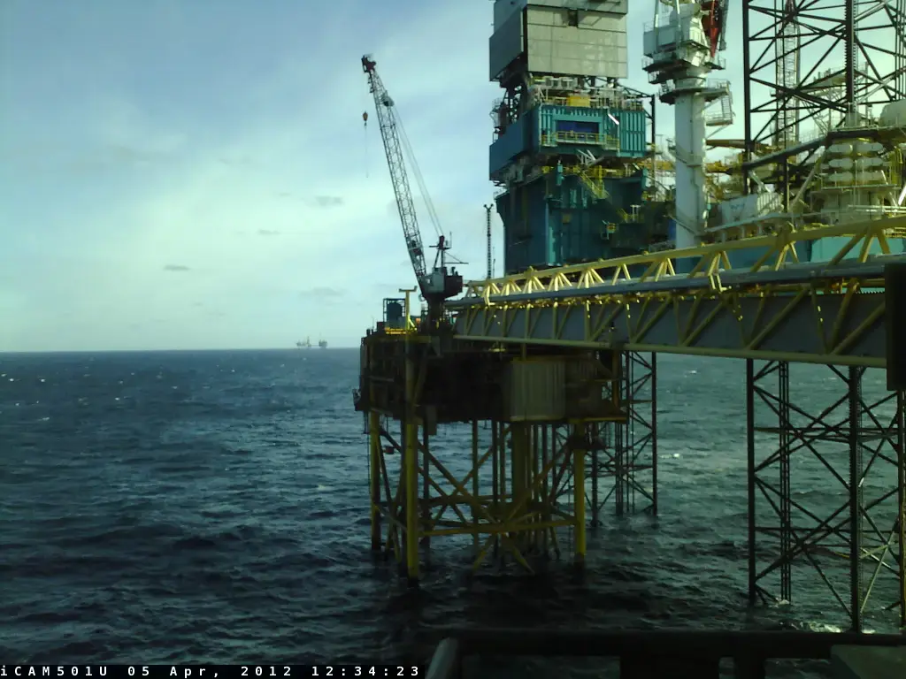
April 5, 2012 - View of the Elgin Well Head Platform
View taken from the Production/Utilities/Quarters (PUQ) platform of the Well Head Platform where the G4 wellhead is situated (April 5, 2012).
Download the photo

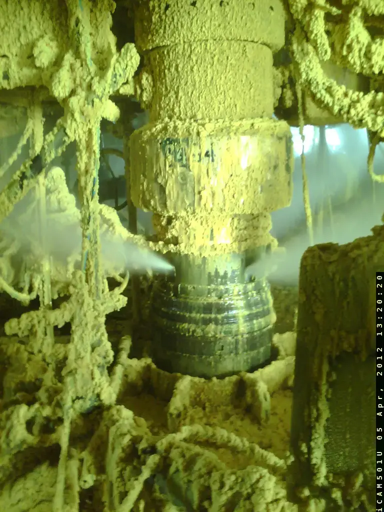
April 5, 2012 - The Elgin G4 wellhead assembly with a view of the source of the gas leak
The Elgin G4 wellhead assembly with a clear view of the source of the gas leak coming out of 4 ports (release points). Localized deposits of condensate and drilling mud were expelled on the wellhead area of the Elgin Well Head Platform at the beginning of the leak and have solidified. This mud contains predominantly a drilling fluid, which is readily biodegradable. This drilling mud is not harmful to the environment.
Download the photo

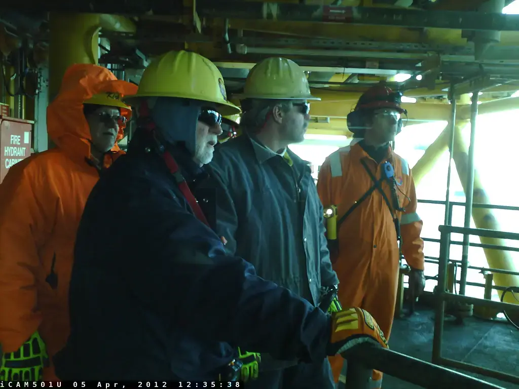
April 5, 2012 - Some members of the reconnaissance team
Some members of the reconnaissance team on Elgin complex on the bridge, before accessing the Well Head Platform on April 5, 2012.
Download the photo

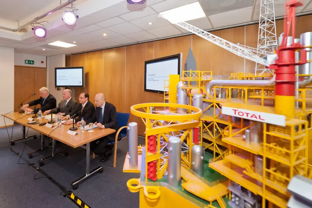
March 30, 2012 - Total E&P UK press conference in Aberdeen
A Total E&P UK press conference in Aberdeen to update the media on the Elgin gas leak, with a detailed scale model of Elgin in the foreground. From left to right are Hugh Shaw (Secretary of State's Representative), Charles Hendry (UK Energy Minister), Philippe Guys (Managing Director of Total E&P UK) and Andrew Hogg (VP Communications E&P).
Download the photo

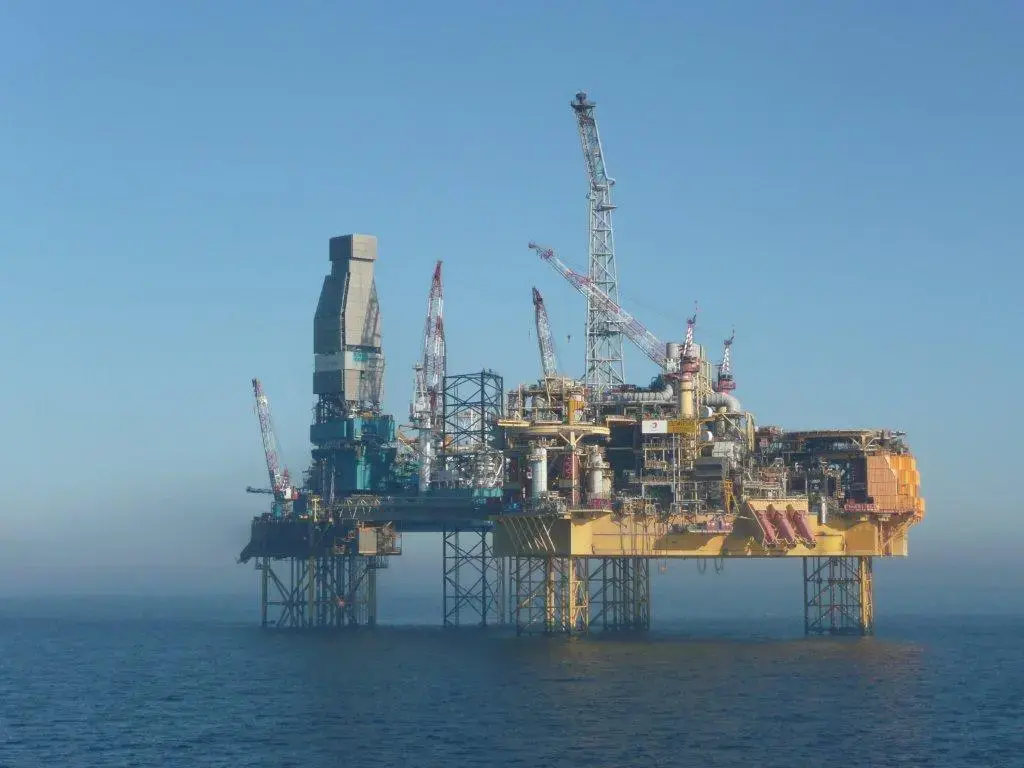
March 27, 2012 at 4:30 pm - Elgin Platform
Elgin Process, Utility and Quarter Platform (PUQ) and Elgin Wellhead Platform (with Rowan Viking drilling rig alongside).
27th March 2012 at 4:30 pm, 52 hours after the incident was first reported.
The Elgin complex was designed specifically so that in the event of incidents such as this one the impact is minimized. For example, there is an 80 m separation between the well head platform and the PUQ platform complex. Also, the orientation of the structure is such that the prevailing winds at the location are most likely to carry any plume away from the complex.
Download the photo

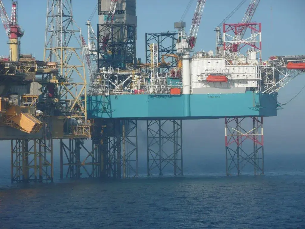
March 27, 2012 at 4:30 pm - The Elgin Platform
Elgin Process, Utility and Quarter Platform (PUQ) and Elgin Wellhead Platform (with Rowan Viking drilling rig alongside).
27th March 2012 at 4:30 pm, 52 hours after the incident was first reported.
The Elgin complex was designed specifically so that in the event of incidents such as this one the impact is minimized. For example, there is an 80 m separation between the well head platform and the PUQ platform complex. Also, the orientation of the structure is such that the prevailing winds at the location are most likely to carry any plume away from the complex.
Download the photo